Materials Designer (MD)
User ViewPoint
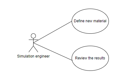
Usage Case Diagram Actors
General Description
The DiMAT Material Designer is a tool dedicated to the calculation of the mechanical and thermal properties of non-homogenous materials, with a specific emphasis on composite materials. The tool encompasses a state-of-the-art Finite Element code able to execute virtual experiments to characterize the new materials starting from the properties of the base materials and their microstructural arrangement.
Model
Roles
Simulation engineer: The simulation engineer uses the DiMAT MD toolkit to calculate the mechanical and thermal properties of a non-homogenous and complex materials defining as inputs the base components with all their properties and the microstructure of the new material. The toolkit provides the requested information and offer the possibility to compare the results to other materials previously analyzed.
Mockups
Activity 1
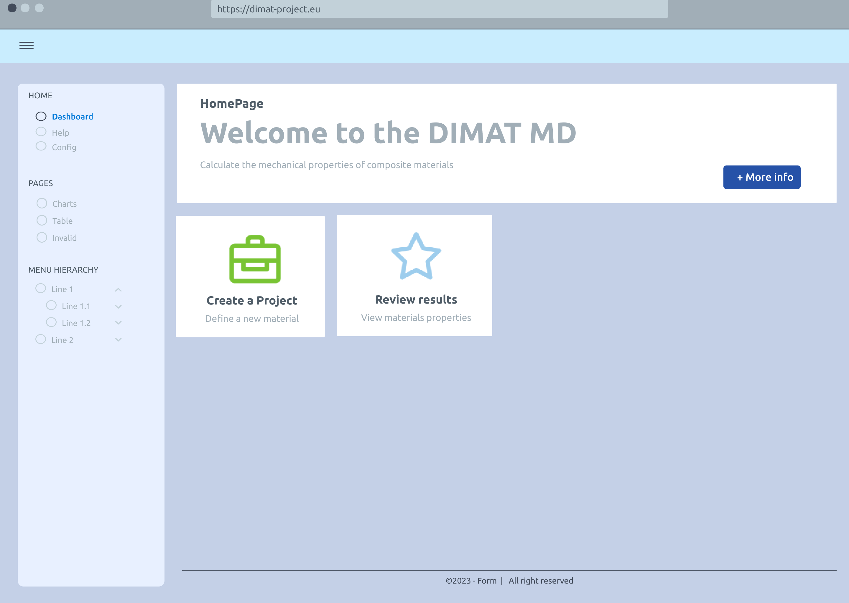
Home page
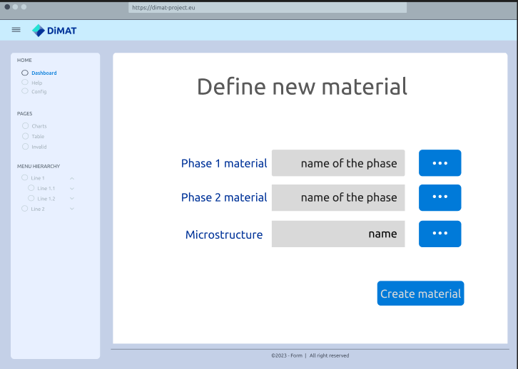
Material definition
Activity 2
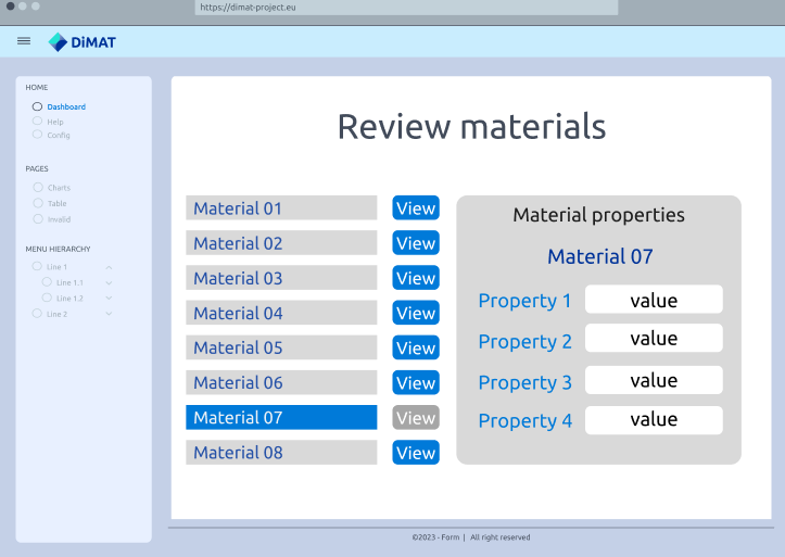
Results review
Functional ViewPoint
General architecture
Implementation ViewPoint
Architecture of Toolkits
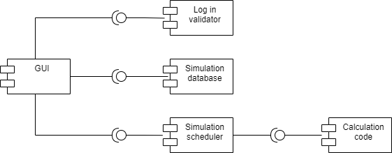
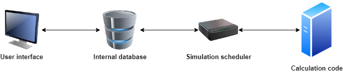
The function of the toolkit is to calculate the material properties of a composite material given its components, their properties, and a chosen microstructure. The core of the toolkit is a commercial code, Hexagon Digimat®, able to execute virtual experiments on a representative volume element of the composite and extract the requested properties from the results. A virtual experiment consists of Finite Element calculation executed on predefined models whose geometry is defined based on the requested microstructure. The general scheme of the internal architecture of the toolkit can be thought as a classic client-server model. The user has direct interaction with the client component, which take care of requesting, storing, and displaying data, while the actual calculation is executed by a server which is totally invisible to the user. The principal components of this toolkit are:
The user interface, where the user ask for material properties and the results are presented.
The internal database, which stores the input of the user and the results obtained.
The simulation scheduler, which manage the interaction between the database and the calculation code.
The calculation code, which executes the virtual experiments. The first three components can be tough as part of the client, while the fourth one is the server. A graphic representation of the described architecture is shown in the next figure.
Required components
Hardware componentes
The simplest scenario consists of just one single machine where all the software is installed and running. This is the case when the license of Digimat® code is locally available. If this is not the case, a more complex scenario is involved, which requires two machines:
Calculation machine, where the Digimat® code is installed, and which oversees executing the FE calculations needed to retrieve the requested data.
Client machine, where data input is requested to the user or data output is shown to him/her.
Data Storage
Different kind of data will be produced and stored in different ways.
Simulation data produced by the FE calculation: the storage is local, on the calculation machine, and not permanent since data are erased once the elaborated data are presented to the user.
Simulation database: this database stores the requested calculations and their results and is located on the client machine.
CMDB: the properties of the material components or the final properties of the composite can be retrieved or uploaded from a CMDB instance.
Implementation Map
The next figure shows how the different components interact starting from the initial input of the user.
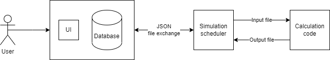
Once the user asks for a specific material configuration to be analysed, the internal simulation database is updated adding the new asked simulation. Then, a json file describing the specific configuration to be analysed is sent to the simulation scheduler, which oversees the communication with the simulation code. The simulation scheduler pre-processes the received JSON file and produces a valid Digimat® input file which is then passed to the code whose execution is triggered. The scheduler, while waiting for other inputs from the user, can retrieve the output data generated by the simulation code and produce a structured JSONfile with the requested output data. The output json data is then processed and the requested material properties are added to the database in the specific record related to the simulation. In the end the user can review the results and, optionally, send them to an instance of the CMDB.